SIDE PANELS FOR 1X1 EXTRUSION. EXTF-7.5
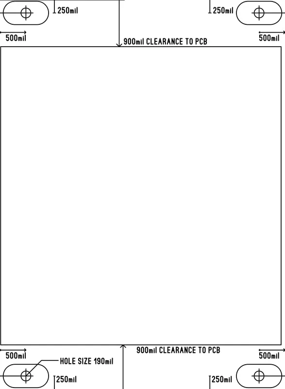
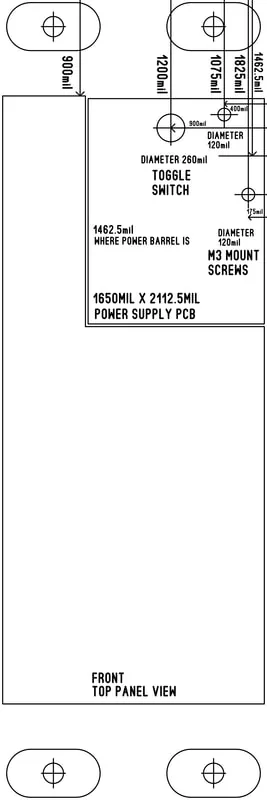
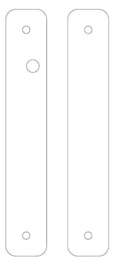
Below is an example of a pair of side panels for EXTF-7.5. The pdf contains all the dimensions needed to drill your own holes.
One side gets a hole for the power barrel.
Power supply specs.
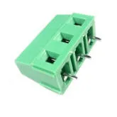
So far I am using screw terminals to power connect multiple modules. This may change later, but it would still be compatible with the screw terminals.
PCB POWER:
TAYDA, DG128 (DG128-03P) (Just an example)
Manufacturer: DEGSON
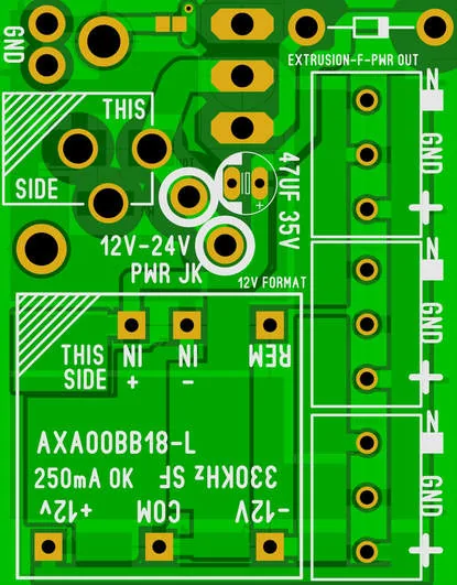
+12v, COM (Ground), -12v. To all designers: please label everything on the pcb to avoid burning circuits.
Here is an example of the labeling I use. This will power 3 items. Some of the modules have another screw terminals to allow daisy chaining modules with power. This power supply can be found on the braids EXTF file on the survival page.
Powering modules involves cutting and stripping your own hookup wire. 14-16 gauge is a good size. I use Red, Black, Yellow or Green or White (Ground) wiring color scheme. Red would be Positive, Black is Negative, and the other color is Ground.
On some of the modules that have on board DC-DC converters. I put input 'DC solder and jumper' to next board locations, so that one power brick was used.
The picture below shows those options.
Please let me know if you design new modules in this format. I can post and promote your stuff here on this site.
Extrusion Format Guide Lines.
EXTF-7.5: This means the panel is 7.5 Inches in height. The physical extrusion case height is 8", rail to rail.
Please keep the width of your panel in 0.0" or 0.5" increments. So one module is 5.5" width, 2.5" width, 4" width, etc. Please don't make a 4.365" wide panel. It will make extrusion cutting easier, and more accurate. Remember to give your extrusion cut a little bit of room, like for a module width of 5.5", i might cut 5.55" worth of extrusion for a single desktop-one module design.
Of course all of this 'width' guide line is if you would like to share room with my designs or someone else's modules.
If you make your own closed design, where modules will not be exchanged ever (like euro format), then do what you want.
The same goes for height. There will one day be EXTF-8.5, EXTF-9, EXT-8.0. Just keep it in 0.0"-0.5"
For Example EXTF-9.5: Panel would be 9.5 inches in height, Extrusion case height would be 10" rail to rail. Side rails would not be hard to calculate. The only reason to go higher in height would be to accommodate more controls.
Why did I even bother with all this?
Luxury control was needed for some fantastic circuits out there.